Steering Sensor Firmware Design
HyTech Racing – Embedded Firmware
Overview
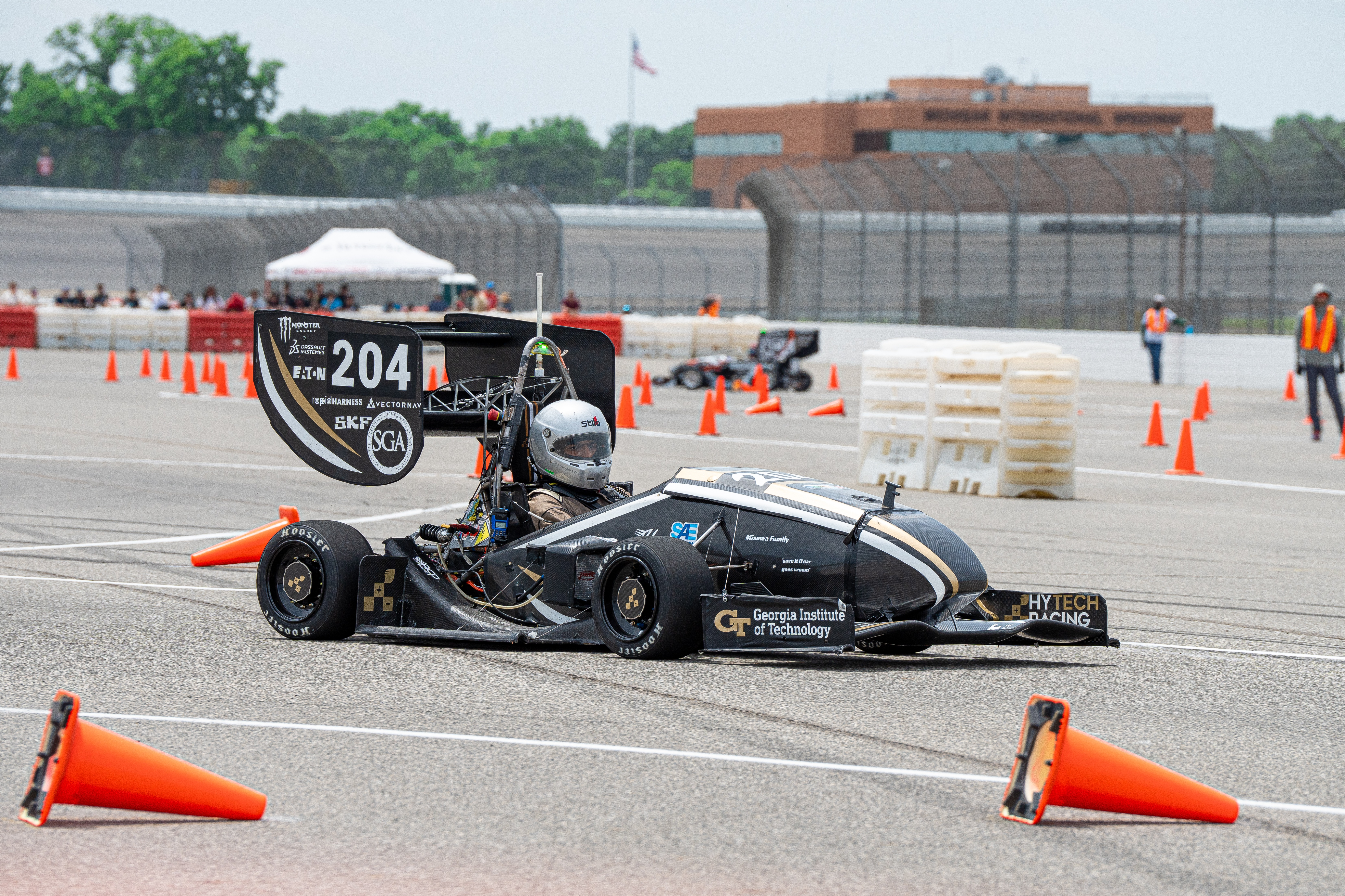
For HyTech’s 2026 FSAE Vehicle: HTX, the electrical subteam needed a steering sensor system to intake values from both an analog and digital steering sensor and run real-time angle critical data for vehicle dynamics, traction control, and telemetry. To accomplish this, I designed and implemented the steering system onto the HTX Vehicle Control Front. System outputs steering angle conversions to the front dashboard, run plausibility checks for our sensor & interface, recalibrates through analyzing vehicle state from Vehicle Control Rear, and sends these values to drivebrain via CAN & Ethernet.
Technical Details
The firmware was written in C++ targeting an teensy 4.1 microcontroller, which also interfaces with an Orbis digital sensor and a Phoenix America analog sensor. Microcontroller intakes analog to digital conversion value from analog sensor and raw reading from the digital sensor, then runs our steering system to conduct necessary functions.
Steering System Design
Initialize Variables
struct SteeringParams_s {
    // raw ADC input signals
    uint32_t min_steering_signal_analog; //Raw ADC value from analog sensor at minimum (left) steering angle (calibration)
    uint32_t max_steering_signal_analog; //Raw ADC value from analog sensor at maximum (right) steering angle
    uint32_t min_steering_signal_digital; //Raw ADC value from digital sensor at minimum (left) steering angle
    uint32_t max_steering_signal_digital; //Raw ADC value from digital sensor at maximum (right) steering angle

    int32_t analog_min_with_margins;
    int32_t analog_max_with_margins;
    int32_t digital_min_with_margins;
    int32_t digital_max_with_margins;

    uint32_t span_signal_analog;
    uint32_t span_signal_digital;
    int32_t digital_midpoint;
    int32_t analog_midpoint;

    // calibration limits
    uint32_t min_observed_digital;
    uint32_t max_observed_digital;
    uint32_t min_observed_analog;
    uint32_t max_observed_analog;

    // conversion rates
    float deg_per_count_analog;
    float deg_per_count_digital;

    // implausibility values
    float analog_tol;
    float analog_tol_deg;
    float digital_tol_deg;

    // rate of angle change
    float max_dtheta_threshold;

    // difference rating
    float error_between_sensors_tolerance;
};

struct SteeringSystemData_s
{
    uint32_t analog_raw;
    uint32_t digital_raw;

    float analog_steering_angle;
    float digital_steering_angle;
    float output_steering_angle;

    float analog_steering_velocity_deg_s;
    float digital_steering_velocity_deg_s;

    bool digital_oor_implausibility;
    bool analog_oor_implausibility;
    bool sensor_disagreement_implausibility;
    bool dtheta_exceeded_analog;
    bool dtheta_exceeded_digital;
    bool both_sensors_fail;
};
Recalibrate
void SteeringSystem::recalibrate_steering_digital() {
    _steeringParams.min_steering_signal_analog = min_observed_analog;
    _steeringParams.max_steering_signal_analog = max_observed_analog;
    _steeringParams.min_steering_signal_digital = min_observed_digital;
    _steeringParams.max_steering_signal_digital = max_observed_digital;
    // swaps  min & max in the params if sensor is flipped
    if (_steeringParams.min_steering_signal_digital > _steeringParams.max_steering_signal_digital) {
        std::swap(_steeringParams.min_steering_signal_digital, _steeringParams.max_steering_signal_digital);
    }
    if (_steeringParams.min_steering_signal_analog > _steeringParams.max_steering_signal_analog) {
        std::swap(_steeringParams.min_steering_signal_analog, _steeringParams.max_steering_signal_analog);
    }
    _steeringParams.span_signal_digital = _steeringParams.max_steering_signal_digital-_steeringParams.min_steering_signal_digital;
    _steeringParams.analog_tol_deg = static_cast<float>(_steeringParams.span_signal_analog) * _steeringParams.analog_tolerance * _steeringParams.deg_per_count_analog;
    _steeringParams.digital_tol_deg = static_cast<float>(_steeringParams.span_signal_digital) *_steeringParams.digital_tolerance * _steeringParams.deg_per_count_digital;
    _steeringParams.digital_midpoint = static_cast<int32_t>((_steeringParams.max_steering_signal_digital + _steeringParams.min_steering_signal_digital) / 2); //NOLINT
    _steeringParams.analog_midpoint = static_cast<int32_t>((_steeringParams.max_steering_signal_analog + _steeringParams.min_steering_signal_analog) / 2); //NOLINT
    _steeringParams.analog_min_with_margins = static_cast<int32_t>(_steeringParams.min_steering_signal_analog) - _steeringParams.analog_tol_deg;
    _steeringParams.analog_max_with_margins = static_cast<int32_t>(_steeringParams.max_steering_signal_analog) + _steeringParams.analog_tol_deg;
    _steeringParams.digital_min_with_margins = static_cast<int32_t>(_steeringParams.min_steering_signal_digital) - _steeringParams.digital_tol_deg;
    _steeringParams.digital_max_with_margins = static_cast<int32_t>(_steeringParams.max_steering_signal_digital) + _steeringParams.digital_tol_deg;

    if (max_observed_analog > min_observed_analog && _steeringParams.span_signal_analog > 2000) // prevents wrap around
    {
        min_observed_analog = UINT32_MAX; // after calculating params, if the range is marginally greater than half the steering wheel adc, likely the min and max are clinging to a prior run that is not applicable, meaning we will need to reset the boundaries.
        max_observed_analog = 0;
    }
    if (max_observed_digital > min_observed_digital && _steeringParams.span_signal_digital > 9000)
    {
        min_observed_digital = UINT32_MAX;
        max_observed_digital = 0;
    }

}

void SteeringSystem::update_observed_steering_limits(const uint32_t analog_raw, const uint32_t digital_raw) {

    min_observed_analog = std::min(min_observed_analog, static_cast<uint32_t>(analog_raw));
    max_observed_analog = std::max(max_observed_analog, static_cast<uint32_t>(analog_raw));
    min_observed_digital = std::min(min_observed_digital, static_cast<uint32_t>(digital_raw)); //NOLINT should both be uint32_t
    max_observed_digital = std::max(max_observed_digital, static_cast<uint32_t>(digital_raw)); //NOLINT ^
    if (min_observed_analog < 5)
    {
        min_observed_analog = UINT32_MAX; // clipping if it is at 0, it is likely sensor is clipping or clipped in past and reading is holding the 0 value.
    }
    if (max_observed_analog > 3685)
    {
        max_observed_analog = 0; // clipping
    }
    if (min_observed_digital < 5)
    {
        min_observed_digital = UINT32_MAX; // clipping on prior run.
    }
    if (max_observed_digital > 16384)
    {
        max_observed_digital = 0; // clipping
    }
}
Converting Values
float SteeringSystem::_convert_digital_sensor(const uint32_t digital_raw) {
    // Same logic for digital
    const int32_t offset =  _steeringParams.digital_midpoint - static_cast<int32_t>(digital_raw); //NOLINT
    return static_cast<float>(offset) * _steeringParams.deg_per_count_digital;
}

float SteeringSystem::_convert_analog_sensor(const uint32_t analog_raw) {
    // Get the raw value
    const int32_t offset = static_cast<int32_t>(analog_raw) - _steeringParams.analog_midpoint; //NOLINT
    return static_cast<float>(offset) * _steeringParams.deg_per_count_analog;
}
Evaluating Out of Range
bool SteeringSystem::_evaluate_steering_oor_analog(const uint32_t steering_analog_raw) { // RAW
    return (static_cast<int32_t>(steering_analog_raw) < _steeringParams.analog_min_with_margins || static_cast<int32_t>(steering_analog_raw) > _steeringParams.analog_max_with_margins);
}

bool SteeringSystem::_evaluate_steering_oor_digital(const uint32_t steering_digital_raw) {// RAW
    return (static_cast<int32_t>(steering_digital_raw) < _steeringParams.digital_min_with_margins || static_cast<int32_t>(steering_digital_raw) > _steeringParams.digital_max_with_margins);
}
Evaluating Steering Speed
bool SteeringSystem::_evaluate_steering_dtheta_exceeded(float steering_velocity_deg_s) {
return (fabs(steering_velocity_deg_s) > _steeringParams.max_dtheta_threshold);
}
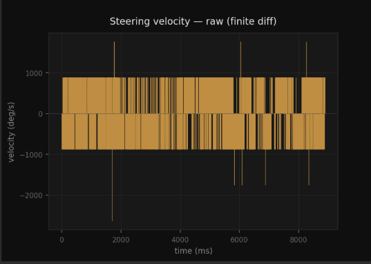
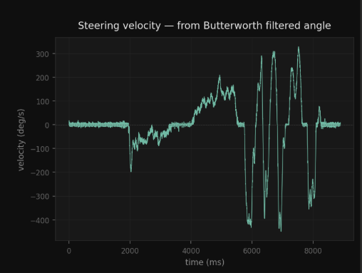
float SteeringSystem::_filter_analog_angle(float x) {
// First sample: pre-load the state so the output starts at x and
// there is no startup transient (otherwise the filter would ramp
// from 0 up to the first real value over ~50 ms).
if (!_bw_initialized) {
_bw_z1 = (1.0f - kBwB0) * x;
_bw_z2 = (kBwB2 - kBwA2) * x;
_bw_initialized = true;
}
// Direct Form II Transposed biquad: 5 multiplies, 4 adds, 2 floats of state.
float y = kBwB0 * x + _bw_z1;
_bw_z1 = kBwB1 * x - kBwA1 * y + _bw_z2;
_bw_z2 = kBwB2 * x - kBwA2 * y;
return y;
}
EVALUATE STEERING CODE:
uint32_t dt = 0;
if (current_millis - _prev_timestamp > 2) {
dt = current_millis - _prev_timestamp; //current_millis is seperate data input
}
if (!_first_run) { //check that we not on the first run which would mean no previous data
if (dt >= 2) {
float filtered_analog_angle = _filter_analog_angle(_convert_analog_sensor(analog_raw));
_steeringSystemData.analog_steering_angle = filtered_analog_angle; // update the angle to the filtered value for downstream use and velocity calculation
float dtheta_analog = filtered_analog_angle - _prev_analog_vel_angle;
float dtheta_digital = _steeringSystemData.digital_steering_angle - _prev_digital_vel_angle;
_steeringSystemData.analog_steering_velocity_deg_s = (dtheta_analog / static_cast<float>(dt)) * 1000.0f;
_steeringSystemData.digital_steering_velocity_deg_s = (dtheta_digital / static_cast<float>(dt)) * 1000.0f;
_last_filtered_analog_angle = filtered_analog_angle;
} else {
_steeringSystemData.analog_steering_angle = _last_filtered_analog_angle;
}
//Update states
if (dt >= 2) { // update at 500Hz
_prev_timestamp = current_millis;
_prev_analog_vel_angle = _steeringSystemData.analog_steering_angle;
_prev_digital_vel_angle = _steeringSystemData.digital_steering_angle;
}
_prev_analog_angle = _steeringSystemData.analog_steering_angle;
_prev_digital_angle = _steeringSystemData.digital_steering_angle;
_first_run = false;
}
Evaluate Steering
void SteeringSystem::evaluate_steering(const uint32_t analog_raw, const SteeringEncoderReading_s digital_data, const uint32_t current_millis) {
    // Reset flags
    _steeringSystemData.digital_oor_implausibility = false;
    _steeringSystemData.analog_oor_implausibility = false;
    _steeringSystemData.sensor_disagreement_implausibility = false;
    _steeringSystemData.dtheta_exceeded_analog = false;
    _steeringSystemData.dtheta_exceeded_digital = false;
    _steeringSystemData.both_sensors_fail = false;

    const uint32_t digital_raw = digital_data.rawValue;

    SteeringEncoderStatus_e digital_status = digital_data.status;
    bool digital_fault = (digital_status == SteeringEncoderStatus_e::ERROR);
    _steeringSystemData.interface_sensor_error = digital_fault;
    _steeringSystemData.digital_raw = digital_raw;

    _steeringSystemData.analog_raw = analog_raw;

    //Conversion from raw ADC to degrees
    _steeringSystemData.digital_steering_angle = _convert_digital_sensor(digital_raw);

    uint32_t dt = 0;
    if (current_millis - _prev_timestamp > 2) {
        dt = current_millis - _prev_timestamp; //current_millis is seperate data input
    }

    if (!_first_run) { //check that we not on the first run which would mean no previous data


        if (dt >= 2) {
            float filtered_analog_angle = _filter_analog_angle(_convert_analog_sensor(analog_raw));
            _steeringSystemData.analog_steering_angle = filtered_analog_angle; // update the angle to the filtered value for downstream use and velocity calculation
            float dtheta_analog = filtered_analog_angle - _prev_analog_vel_angle;
            float dtheta_digital = _steeringSystemData.digital_steering_angle - _prev_digital_vel_angle;

            _steeringSystemData.analog_steering_velocity_deg_s = (dtheta_analog / static_cast<float>(dt)) * 1000.0f;

            _steeringSystemData.digital_steering_velocity_deg_s = (dtheta_digital / static_cast<float>(dt)) * 1000.0f;

            _last_filtered_analog_angle = filtered_analog_angle;
        } else {
            _steeringSystemData.analog_steering_angle = _last_filtered_analog_angle;
        }


        //Check if either sensor moved too much in one tick
        _steeringSystemData.dtheta_exceeded_analog = _evaluate_steering_dtheta_exceeded(_steeringSystemData.analog_steering_velocity_deg_s);
        _steeringSystemData.dtheta_exceeded_digital = _evaluate_steering_dtheta_exceeded(_steeringSystemData.digital_steering_velocity_deg_s); // use digital velocity for dtheta check since it's more precise and we are concerned about large changes in angle that could be caused by noise in the analog sensor

        //Check if either sensor is out of range (pass in raw)
        _steeringSystemData.analog_oor_implausibility = _evaluate_steering_oor_analog(static_cast<uint32_t>(analog_raw));
        _steeringSystemData.digital_oor_implausibility = _evaluate_steering_oor_digital(static_cast<uint32_t>(digital_raw));

        //Check if there is too much of a difference between sensor values
        float sensor_difference = std::fabs(_steeringSystemData.analog_steering_angle - _steeringSystemData.digital_steering_angle);
        bool sensors_agree = (sensor_difference <= _steeringParams.error_between_sensors_tolerance); //steeringParams.error
        _steeringSystemData.sensor_disagreement_implausibility = !sensors_agree;

        //create an algorithm/ checklist to determine which sensor we trust more,
        //or, if we should have an algorithm to have a weighted calculation based on both values
        bool analog_valid = !_steeringSystemData.analog_oor_implausibility && !_steeringSystemData.dtheta_exceeded_analog;
        bool digital_valid = !_steeringSystemData.digital_oor_implausibility && !_steeringSystemData.dtheta_exceeded_digital && !_steeringSystemData.interface_sensor_error;

        if (analog_valid && digital_valid) {
            //if sensors have acceptable difference, use digital as steering angle
            if (sensors_agree) {
                _steeringSystemData.output_steering_angle = _steeringSystemData.digital_steering_angle;
            } else {
                _steeringSystemData.output_steering_angle = _steeringSystemData.digital_steering_angle; //default to original, but we need to consider what we really want to put here
            }
        } else if (analog_valid) {
            _steeringSystemData.output_steering_angle = _steeringSystemData.analog_steering_angle;
        } else if (digital_valid) {
            _steeringSystemData.output_steering_angle = _steeringSystemData.digital_steering_angle;
        } else { // if both sensors fail
            _steeringSystemData.output_steering_angle = _prev_digital_angle;
            _steeringSystemData.both_sensors_fail = true;
        }
    }
    //Update states
    if (dt >= 2) { // update at 500Hz
        _prev_timestamp = current_millis;
        _prev_analog_vel_angle = _steeringSystemData.analog_steering_angle;
        _prev_digital_vel_angle = _steeringSystemData.digital_steering_angle;
    }

    _prev_analog_angle = _steeringSystemData.analog_steering_angle;
    _prev_digital_angle = _steeringSystemData.digital_steering_angle;
    _first_run = false;
}
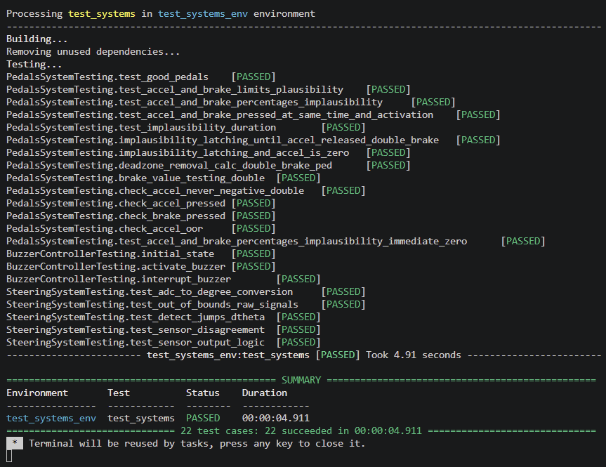
Unit Tests
true, false, EXPECT_EQ, or EXPECT_NEAR within a thousandth of a degree to catch floating-point drift. The tests not shown here follow the same pattern: feed a modified input into the steering system and confirm the output changes as expected. This does not show all of the unit tests, but does give an idea for the approach.
#define STEERING_SYSTEM_TEST
#include <gtest/gtest.h>
#include <string>
#include "SteeringSystem.h"
#include "SharedFirmwareTypes.h"
#include <array>
#include <iostream>

SteeringParams_s gen_default_params(){
    SteeringParams_s params{};
    //hard code the parmas for sensors
    params.min_steering_signal_analog = 1024;
    params.max_steering_signal_analog = 3071;//actual hard coded

    params.min_steering_signal_digital = 25;
    params.max_steering_signal_digital = 8000; //testing values

    params.span_signal_analog = 4095;
    params.span_signal_digital = 8000;

    params.min_observed_digital = 2000;
    params.max_observed_digital = 6000;

    params.deg_per_count_analog = 0.087890625f;
    params.deg_per_count_digital = 0.02197265625f;

    params.analog_tol = 0.005f;
    params.analog_tol_deg = 0.11377778f;
    params.digital_tol_deg = 0.2f;

    params.max_dtheta_threshold = 5.0f;//change
    params.error_between_sensors_tolerance = 0.31377778f;

    params.digital_midpoint = (params.min_steering_signal_digital + params.max_steering_signal_digital) / 2;
    params.analog_midpoint = (params.min_steering_signal_analog + params.max_steering_signal_analog) / 2;

    const int32_t analog_margin_counts = static_cast<int32_t>(params.analog_tol * static_cast<float>(params.span_signal_analog));
    const int32_t digital_margin_counts = static_cast<int32_t>(params.digital_tol_deg / params.deg_per_count_digital);

    params.analog_min_with_margins = static_cast<int32_t>(params.min_steering_signal_analog) - analog_margin_counts;
    params.analog_max_with_margins = static_cast<int32_t>(params.max_steering_signal_analog) + analog_margin_counts;
    params.digital_min_with_margins = static_cast<int32_t>(params.min_steering_signal_digital) - digital_margin_counts;
    params.digital_max_with_margins = static_cast<int32_t>(params.max_steering_signal_digital) + digital_margin_counts;
    return params;
}

void debug_print_steering(const SteeringSystemData_s& data){
    std::cout << "analog_steering_angle: "  << data.analog_steering_angle << " deg\n";
    std::cout << "digital_steering_angle: " << data.digital_steering_angle << " deg\n";
    std::cout << "output_steering_angle: "  << data.output_steering_angle << " deg\n";
    std::cout << "analog_oor_implausibility: "          << data.analog_oor_implausibility << "\n";
    std::cout << "digital_oor_implausibility: "         << data.digital_oor_implausibility << "\n";
    std::cout << "sensor_disagreement_implausibility: " << data.sensor_disagreement_implausibility << "\n";
    std::cout << "dtheta_exceeded_analog: "  << data.dtheta_exceeded_analog << "\n";
    std::cout << "dtheta_exceeded_digital: " << data.dtheta_exceeded_digital << "\n";
}

TEST(SteeringSystemTesting, test_adc_to_degree_conversion)
{
    auto params = gen_default_params();
    SteeringSystem steering(params);

    uint32_t analog_mid = (params.min_steering_signal_analog + params.max_steering_signal_analog) / 2;
    uint32_t digital_mid = (params.min_steering_signal_digital + params.max_steering_signal_digital) / 2;

    //midpoints
    SteeringSensorData_s midpoint{};
    midpoint.analog_steering_degrees = analog_mid;
    midpoint.digital_steering_analog = digital_mid;
    steering.evaluate_steering(midpoint, 1000);
    auto data = steering.get_steering_system_data();
    EXPECT_NEAR(data.analog_steering_angle, 0.0f, 0.001f);
    EXPECT_NEAR(data.digital_steering_angle, 0.0f, 0.001f);

    //min values
    SteeringSensorData_s min_val{};
    min_val.analog_steering_degrees = params.min_steering_signal_analog;
    min_val.digital_steering_analog = params.min_steering_signal_digital;
    steering.evaluate_steering(min_val, 1010);
    data = steering.get_steering_system_data();

    float expected_analog_min = (static_cast<int32_t>(params.min_steering_signal_analog) - static_cast<int32_t>(analog_mid)) * params.deg_per_count_analog;
    float expected_digital_min = (static_cast<int32_t>(params.min_steering_signal_digital) - static_cast<int32_t>(digital_mid)) * params.deg_per_count_digital;
    EXPECT_NEAR(data.analog_steering_angle, expected_analog_min, 0.001f);
    EXPECT_NEAR(data.digital_steering_angle, expected_digital_min, 0.001f);

    //max values
    SteeringSensorData_s max_val{};
    max_val.analog_steering_degrees = params.max_steering_signal_analog;
    max_val.digital_steering_analog = params.max_steering_signal_digital;
    steering.evaluate_steering(max_val, 1020);
    data = steering.get_steering_system_data();

    float expected_analog_max = (static_cast<int32_t>(params.max_steering_signal_analog) - static_cast<int32_t>(analog_mid)) * params.deg_per_count_analog;
    float expected_digital_max = (static_cast<int32_t>(params.max_steering_signal_digital) - static_cast<int32_t>(digital_mid)) * params.deg_per_count_digital;
    EXPECT_NEAR(data.analog_steering_angle, expected_analog_max, 0.001f);
    EXPECT_NEAR(data.digital_steering_angle, expected_digital_max, 0.001f);
}

TEST(SteeringSystemTesting, test_sensor_output_logic){
    auto params = gen_default_params();

    uint32_t analog_mid = (params.min_steering_signal_analog + params.max_steering_signal_analog) / 2;
    uint32_t digital_mid = (params.min_steering_signal_digital + params.max_steering_signal_digital) / 2;

{
    //When both valid and agreeing, we default to digital
    SteeringSystem steering(params);
    SteeringSensorData_s both_valid {};
    both_valid.analog_steering_degrees = analog_mid;
    both_valid.digital_steering_analog = digital_mid;
    steering.evaluate_steering(both_valid, 1000);
    steering.evaluate_steering(both_valid, 1100);
    auto data = steering.get_steering_system_data();
    EXPECT_NEAR(data.output_steering_angle, data.digital_steering_angle, 0.001f);
    EXPECT_FALSE(data.both_sensors_fail);
    EXPECT_FALSE(data.sensor_disagreement_implausibility);
}
{
    //When both valid but disagreeing, we default to digital
    SteeringSystem steering(params);
    SteeringSensorData_s both_valid_disagree {};
    both_valid_disagree.analog_steering_degrees = analog_mid;
    both_valid_disagree.digital_steering_analog = digital_mid+3000; //large offset from analog
    steering.evaluate_steering(both_valid_disagree, 1000);
    steering.evaluate_steering(both_valid_disagree, 1100);
    auto data = steering.get_steering_system_data();
    EXPECT_TRUE(data.sensor_disagreement_implausibility);
    EXPECT_FALSE(data.analog_oor_implausibility);
    EXPECT_FALSE(data.digital_oor_implausibility);
    EXPECT_NEAR(data.output_steering_angle, data.digital_steering_angle, 0.001f);
}
{
    //When analog is good but digital is bad, we put analog
    SteeringSystem steering(params);
    SteeringSensorData_s digital_bad {};
    digital_bad.analog_steering_degrees = analog_mid;
    digital_bad.digital_steering_analog = params.max_steering_signal_digital + 1000; //bad digital
    steering.evaluate_steering(digital_bad, 1000);
    steering.evaluate_steering(digital_bad, 1100);
    auto data = steering.get_steering_system_data();
    EXPECT_TRUE(data.digital_oor_implausibility);
    EXPECT_FALSE(data.analog_oor_implausibility);
    EXPECT_NEAR(data.output_steering_angle, data.analog_steering_angle, 0.001f);
}
{
    //When digital is good but analog is bad, we put digital
    SteeringSystem steering(params);
    SteeringSensorData_s analog_bad {};
    analog_bad.analog_steering_degrees = params.max_steering_signal_analog + 1000;
    analog_bad.digital_steering_analog = digital_mid;
    steering.evaluate_steering(analog_bad, 1000);
    steering.evaluate_steering(analog_bad, 1005);
    auto data = steering.get_steering_system_data();
    EXPECT_TRUE(data.analog_oor_implausibility);
    EXPECT_FALSE(data.digital_oor_implausibility);
    EXPECT_NEAR(data.output_steering_angle, data.digital_steering_angle, 0.001f);
}
{
    //When both bad, we flag that error
    SteeringSystem steering(params);
    SteeringSensorData_s both_bad {};
    both_bad.analog_steering_degrees = params.max_steering_signal_analog + 1000;
    both_bad.digital_steering_analog = params.max_steering_signal_digital + 1000;
    steering.evaluate_steering(both_bad, 1000);
    steering.evaluate_steering(both_bad, 1005);
    auto data = steering.get_steering_system_data();
    EXPECT_TRUE(data.analog_oor_implausibility);
    EXPECT_TRUE(data.digital_oor_implausibility);
    EXPECT_TRUE(data.both_sensors_fail);
}
}
VCF System Design
Setup All Interfaces
void setup_all_interfaces() {
    SPI.begin();
    Serial.begin(VCFTaskConstants::SERIAL_BAUDRATE); // NOLINT
    ADCInterfaceInstance::create(
    // Initialize all singletons
    ADCChannels_s {
        VCFInterfaceConstants::STEERING_1_CHANNEL,
        VCFInterfaceConstants::STEERING_2_CHANNEL,
    },
    ADCScales_s {
        VCFInterfaceConstants::STEERING_1_SCALE,
        VCFInterfaceConstants::STEERING_2_SCALE,
    },
    ADCOffsets_s {
        VCFInterfaceConstants::STEERING_1_OFFSET,
        VCFInterfaceConstants::STEERING_2_OFFSET,
    });
    EthernetIPDefsInstance::create();

    SteeringParams_s steering_params = {
        .min_steering_signal_analog = VCFSystemConstants::MIN_STEERING_SIGNAL_ANALOG,
        .max_steering_signal_analog = VCFSystemConstants::MAX_STEERING_SIGNAL_ANALOG,
        .min_steering_signal_digital = EEPROMUtilities::read_eeprom_32bit(VCFSystemConstants::MIN_STEERING_SIGNAL_DIGITAL_ADDR),
        .max_steering_signal_digital = EEPROMUtilities::read_eeprom_32bit(VCFSystemConstants::MAX_STEERING_SIGNAL_DIGITAL_ADDR),
        .analog_min_with_margins = EEPROMUtilities::read_eeprom_32bit(VCFSystemConstants::ANALOG_MIN_WITH_MARGINS_ADDR),
        .analog_max_with_margins = EEPROMUtilities::read_eeprom_32bit(VCFSystemConstants::ANALOG_MAX_WITH_MARGINS_ADDR),
        .digital_min_with_margins = EEPROMUtilities::read_eeprom_32bit(VCFSystemConstants::DIGITAL_MIN_WITH_MARGINS_ADDR),
        .digital_max_with_margins = EEPROMUtilities::read_eeprom_32bit(VCFSystemConstants::DIGITAL_MAX_WITH_MARGINS_ADDR),
        .span_signal_analog = VCFSystemConstants::SPAN_SIGNAL_ANALOG,
        .analog_midpoint = VCFSystemConstants::ANALOG_MIDPOINT,
        .deg_per_count_analog = VCFSystemConstants::DEG_PER_COUNT_ANALOG,
        .deg_per_count_digital = VCFSystemConstants::DEG_PER_COUNT_DIGITAL,
        .analog_tol = VCFSystemConstants::ANALOG_TOL,
        .digital_tol_deg = VCFSystemConstants::DIGITAL_TOL_DEG,
        .max_dtheta_threshold = VCFSystemConstants::MAX_DTHETA_THRESHOLD,
    };
    steering_params.span_signal_digital = steering_params.max_steering_signal_digital - steering_params.min_steering_signal_digital;
    steering_params.digital_midpoint = (steering_params.min_steering_signal_digital + steering_params.max_steering_signal_digital) / 2;
    steering_params.analog_tol_deg = static_cast<float>(steering_params.span_signal_analog) * steering_params.analog_tol * steering_params.deg_per_count_analog;
    steering_params.error_between_sensors_tolerance = steering_params.analog_tol_deg + steering_params.digital_tol_deg;

    SteeringSystemInstance::create(steering_params);

    // Create Digital Steering Sensor singleton
    OrbisBRInstance::create(&Serial2);
}
Async Main Task
namespace async_tasks
{
    void handle_async_CAN_receive() //NOLINT caps for CAN
    {
        VCFCANInterfaceObjects& vcf_interface_objects = VCFCANInterfaceImpl::VCFCANInterfaceObjectsInstance::instance();
        CANInterfaces& vcf_can_interfaces = VCFCANInterfaceImpl::CANInterfacesInstance::instance();
        process_ring_buffer(vcf_interface_objects.main_can_rx_buffer, vcf_can_interfaces, sys_time::hal_millis(), vcf_interface_objects.can_recv_switch, CANInterfaceType_e::TELEM);
    }
    void handle_async_recvs()
    {
        // ethernet, etc...
        handle_async_CAN_receive();
    }
    HT_TASK::TaskResponse handle_async_main(const unsigned long& sys_micros, const HT_TASK::TaskInfo& task_info)
    {
        handle_async_recvs();
        OrbisBRInstance::instance().sample();
        const uint32_t analog_raw = static_cast<uint32_t>(ADCInterfaceInstance::instance().steering_degrees_cw().raw);
        const SteeringEncoderConversion_s digital_data = OrbisBRInstance::instance().convert();
        SteeringSystemInstance::instance().evaluate_steering(
            analog_raw,
            digital_data,
            sys_time::hal_millis()
        );

        PedalsSystemInstance::instance().evaluate_pedals(
            PedalsSystemInstance::instance().get_pedals_sensor_data(),
            sys_time::hal_millis()
        );
        return HT_TASK::TaskResponse::YIELD;
    }
};
Update Steering Calibration Task
uint32_t last_steering_calibrate_time; // move this maybe
HT_TASK::TaskResponse update_steering_calibration_task(const unsigned long& sysMicros, const HT_TASK::TaskInfo& taskInfo) {
    const uint32_t analog_raw = SteeringSystemInstance::instance().get_steering_system_data().analog_raw;
    const uint32_t digital_raw = SteeringSystemInstance::instance().get_steering_system_data().digital_raw;

    SteeringSystemInstance::instance().update_observed_steering_limits(analog_raw, digital_raw);


     if (VCRInterfaceInstance::instance().is_in_steering_calibration_state() && sys_time::hal_millis() - last_steering_calibrate_time > 5000) {
        last_steering_calibrate_time = sys_time::hal_millis();

        SteeringSystemInstance::instance().recalibrate_steering_digital();
        EEPROMUtilities::write_eeprom_32bit(VCFSystemConstants::MIN_STEERING_SIGNAL_ANALOG_ADDR, SteeringSystemInstance::instance().get_steering_params().min_steering_signal_analog);
        EEPROMUtilities::write_eeprom_32bit(VCFSystemConstants::MAX_STEERING_SIGNAL_ANALOG_ADDR, SteeringSystemInstance::instance().get_steering_params().max_steering_signal_analog);
        EEPROMUtilities::write_eeprom_32bit(VCFSystemConstants::MIN_STEERING_SIGNAL_DIGITAL_ADDR, SteeringSystemInstance::instance().get_steering_params().min_steering_signal_digital);
        EEPROMUtilities::write_eeprom_32bit(VCFSystemConstants::MAX_STEERING_SIGNAL_DIGITAL_ADDR, SteeringSystemInstance::instance().get_steering_params().max_steering_signal_digital);
        EEPROMUtilities::write_eeprom_32bit(VCFSystemConstants::ANALOG_MIN_WITH_MARGINS_ADDR, SteeringSystemInstance::instance().get_steering_params().analog_min_with_margins);
        EEPROMUtilities::write_eeprom_32bit(VCFSystemConstants::ANALOG_MAX_WITH_MARGINS_ADDR, SteeringSystemInstance::instance().get_steering_params().analog_max_with_margins);
        EEPROMUtilities::write_eeprom_32bit(VCFSystemConstants::DIGITAL_MIN_WITH_MARGINS_ADDR, SteeringSystemInstance::instance().get_steering_params().digital_min_with_margins);
        EEPROMUtilities::write_eeprom_32bit(VCFSystemConstants::DIGITAL_MAX_WITH_MARGINS_ADDR, SteeringSystemInstance::instance().get_steering_params().digital_max_with_margins);

}
Constants
    constexpr int STEERING_1_CHANNEL        = 2;    // Analog steering sensor 1
constexpr int BTN_PRESET_READ = 28; // recal button (brightness control on schematic)
constexpr float STEERING_1_OFFSET = 0;

namespace VCFSystemConstants {

    // Steering System Constants
    constexpr uint32_t MIN_STEERING_SIGNAL_ANALOG_ADDR = 56; //Raw ADC value from analog sensor at minimum (left) steering angle (calibration) TODO: test and find real values for min&max
    constexpr uint32_t MAX_STEERING_SIGNAL_ANALOG_ADDR = 60; //Raw ADC value from analog sensor at maximum (right) steering angle
    constexpr uint32_t MIN_STEERING_SIGNAL_DIGITAL_ADDR = 32; //Raw ADC value from digital sensor at minimum (left) steering angle
    constexpr uint32_t MAX_STEERING_SIGNAL_DIGITAL_ADDR = 36; //Raw ADC value from digital sensor at maximum (right) steering angle

    constexpr int32_t ANALOG_MIN_WITH_MARGINS_ADDR = 40;
    constexpr int32_t ANALOG_MAX_WITH_MARGINS_ADDR = 44;
    constexpr int32_t DIGITAL_MIN_WITH_MARGINS_ADDR = 48;
    constexpr int32_t DIGITAL_MAX_WITH_MARGINS_ADDR = 52;

    // implausibility values
    constexpr float ANALOG_TOLERANCE = 0.05f; //+- 0.5% error (analog sensor tolerance according to datasheet)
    constexpr float DIGITAL_TOLERANCE = 0.05f; // +- 0.2 degrees error
    constexpr float ERROR_BETWEEN_SENSORS_TOLERANCE = 5.0f;

    // rate of angle change
    constexpr float MAX_DTHETA_THRESHOLD = 50.0f; //maximum change in angle since last reading to consider the reading valid

    // degrees per bit
    constexpr float DEG_PER_COUNT_DIGITAL = 360.0f / 16384.0f;
    constexpr float DEG_PER_COUNT_ANALOG = 360.0f / 3686.4f;
}

namespace VCFTaskConstants {
    constexpr unsigned long CAN_SEND_PRIORITY = 10;
    constexpr unsigned long CAN_SEND_PERIOD = 2000;               // 2 000 us = 500 Hz
    constexpr unsigned long DASH_SEND_PERIOD = 100000;            // 100 000 us = 10 Hz
    constexpr unsigned long DASH_SEND_PRIORITY = 7;
    constexpr unsigned long DEBUG_PRIORITY = 100;
    constexpr unsigned long DEBUG_PERIOD = 10000;                 // 10 000 us = 100 Hz
    constexpr unsigned long STEERING_SEND_PERIOD = 4000;          // 4 000 us = 250 Hz
    constexpr unsigned long STEERING_SEND_PRIORITY = 25;
    constexpr unsigned long STEERING_SAMPLE_PERIOD = 1000;        // 1 000 us = 1000 Hz
    constexpr unsigned long STEERING_SAMPLE_PRIORITY = 10;
    constexpr unsigned long ETHERNET_SEND_PERIOD = 100000;        // 100 000 us = 10 Hz
    constexpr unsigned long ETHERNET_SEND_PRIORITY = 20;
    constexpr unsigned long STEERING_RECALIBRATION_PRIORITY = 150; // TODO: Determine real values for these
    constexpr unsigned long STEERING_RECALIBRATION_PERIOD = 100000;
}
Debug Prints
// HT_TASK::TaskResponse debug_print(const unsigned long& sysMicros, const HT_TASK::TaskInfo& taskInfo)
{    Serial.println("--------------------------------------------------");

    Serial.println("Steering Sensor Data: ");
    Serial.print("analog: ");
    Serial.print(SteeringSystemInstance::instance().get_steering_system_data().analog_raw);
    Serial.print("|");
    Serial.println(SteeringSystemInstance::instance().get_steering_system_data().analog_steering_angle);
    Serial.print("digital: ");
    Serial.print(SteeringSystemInstance::instance().get_steering_system_data().digital_raw);
    Serial.print("|");
    Serial.println(SteeringSystemInstance::instance().get_steering_system_data().digital_steering_angle);

    Serial.print("analog_steering_angle: ");
    Serial.println(SteeringSystemInstance::instance().get_steering_system_data().analog_steering_angle);
    Serial.print("digital_steering_angle: ");
    Serial.println(SteeringSystemInstance::instance().get_steering_system_data().digital_steering_angle);

    Serial.print("output_steering_angle: ");
    Serial.println(SteeringSystemInstance::instance().get_steering_system_data().output_steering_angle);

    Serial.print("analog_steering_velocity_deg_s: ");
    Serial.println(SteeringSystemInstance::instance().get_steering_system_data().analog_steering_velocity_deg_s);
    Serial.print("digital_steering_velocity_deg_s: ");
    Serial.println(SteeringSystemInstance::instance().get_steering_system_data().digital_steering_velocity_deg_s);

    Serial.print("digital_oor_implausibility: ");
    Serial.println(SteeringSystemInstance::instance().get_steering_system_data().digital_oor_implausibility);
    Serial.print("analog_oor_implausibility: ");
    Serial.println(SteeringSystemInstance::instance().get_steering_system_data().analog_oor_implausibility);
    Serial.print("sensor_disagreement_implausibility: ");
    Serial.println(SteeringSystemInstance::instance().get_steering_system_data().sensor_disagreement_implausibility);
    Serial.print("dtheta_exceeded_analog: ");
    Serial.println(SteeringSystemInstance::instance().get_steering_system_data().dtheta_exceeded_analog);
    Serial.print("dtheta_exceeded_digital: ");
    Serial.println(SteeringSystemInstance::instance().get_steering_system_data().dtheta_exceeded_digital);
    Serial.print("both_sensors_fail: ");
    Serial.println(SteeringSystemInstance::instance().get_steering_system_data().both_sensors_fail);
    Serial.print("interface_sensor_error: ");
    Serial.println(SteeringSystemInstance::instance().get_steering_system_data().interface_sensor_error);

    return HT_TASK::TaskResponse::YIELD;
}
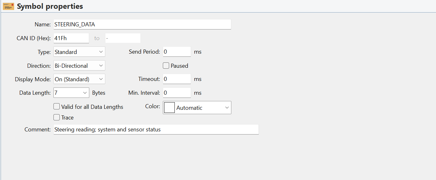
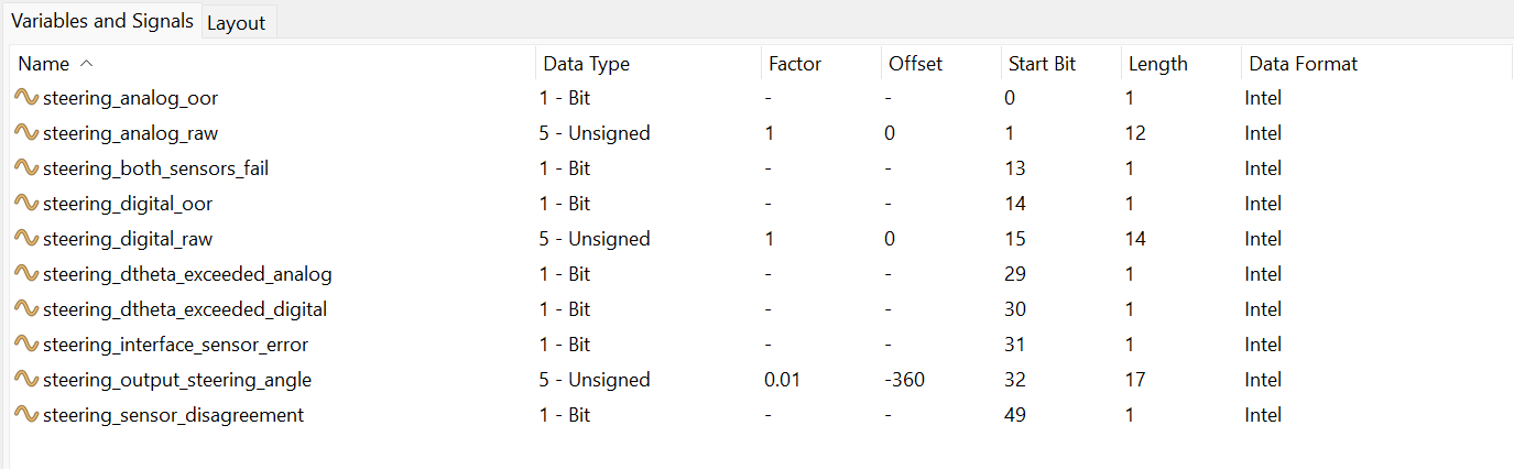
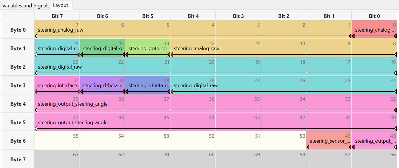
CAN Send
HT_TASK::TaskResponse enqueue_steering_data(const unsigned long& sysMicros, const HT_TASK::TaskInfo& taskInfo)
{
STEERING_DATA_t msg_out;
SteeringSystemData_s steering_system_data = SteeringSystemInstance::instance().get_steering_system_data();
msg_out.steering_analog_oor = steering_system_data.analog_oor_implausibility;
msg_out.steering_both_sensors_fail = steering_system_data.both_sensors_fail;
msg_out.steering_digital_oor = steering_system_data.digital_oor_implausibility;
msg_out.steering_dtheta_exceeded_analog = steering_system_data.dtheta_exceeded_analog;
msg_out.steering_dtheta_exceeded_digital = steering_system_data.dtheta_exceeded_digital;
msg_out.steering_interface_sensor_error = steering_system_data.interface_sensor_error;
msg_out.steering_output_steering_angle_ro = HYTECH_steering_output_steering_angle_ro_toS(steering_system_data.output_steering_angle);
msg_out.steering_sensor_disagreement = steering_system_data.sensor_disagreement_implausibility;
msg_out.steering_analog_raw = steering_system_data.analog_steering_angle;
msg_out.steering_digital_raw = steering_system_data.digital_steering_angle;
CAN_util::enqueue_msg(&msg_out, &Pack_STEERING_DATA_hytech, VCFCANInterfaceImpl::VCFCANInterfaceObjectsInstance::instance().main_can_tx_buffer);
return HT_TASK::TaskResponse::YIELD;
}
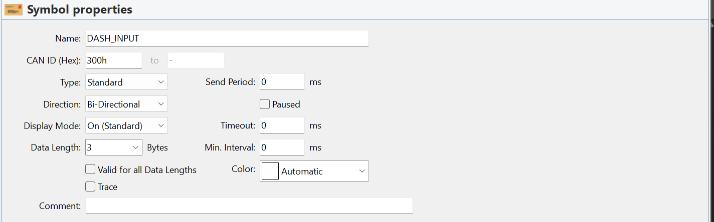
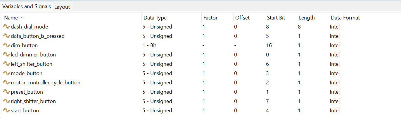
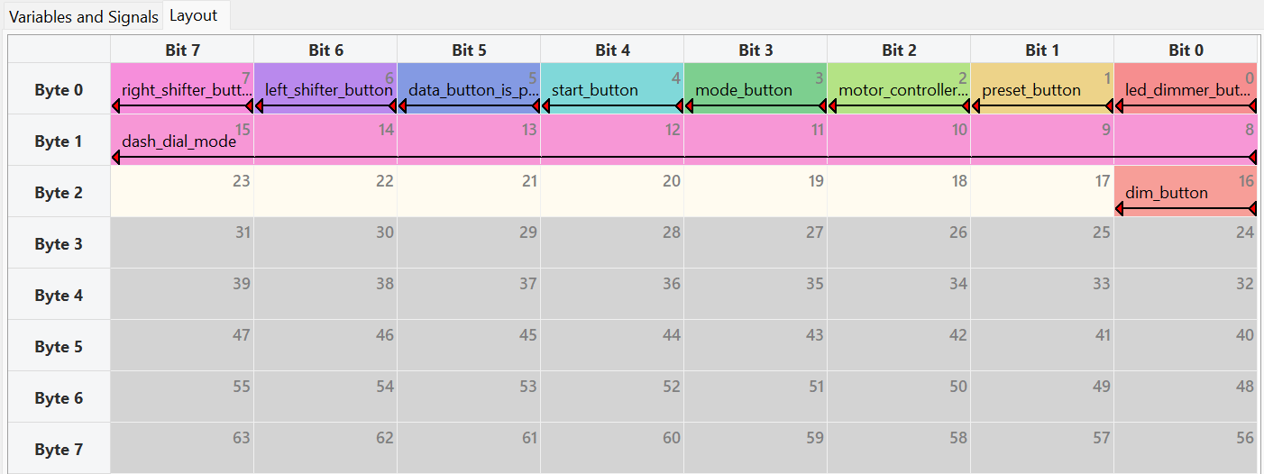
HT_TASK::TaskResponse send_dash_data(const unsigned long& sysMicros, const HT_TASK::TaskInfo& taskInfo)
{
CANInterfaces can_interfaces = VCFCANInterfaceImpl::CANInterfacesInstance::instance();
DashInputState_s dash_outputs = can_interfaces.dash_interface.get_dashboard_outputs();
DASH_INPUT_t msg_out;
//for this, add a message for the new button when its here, for now, steering system linked to dim_button.
msg_out.dim_button = dash_outputs.btn_dim_read_is_pressed;
msg_out.preset_button = dash_outputs.preset_btn_is_pressed;
msg_out.mode_button = 0; // dont exist but i dont wanna bother changing can msgs
msg_out.motor_controller_cycle_button = dash_outputs.mc_reset_btn_is_pressed;
msg_out.start_button = dash_outputs.start_btn_is_pressed;
msg_out.data_button_is_pressed = dash_outputs.data_btn_is_pressed;
msg_out.left_shifter_button = 0;
msg_out.right_shifter_button = dash_outputs.BUTTON_2;
msg_out.led_dimmer_button = dash_outputs.brightness_ctrl_btn_is_pressed;
msg_out.dash_dial_mode = static_cast<int>(DashboardInterfaceInstance::instance().get_dashboard_outputs().dial_state);
// Serial.printf("%d %d %d %d %d %d %d %d\n", msg_out.preset_button, msg_out.motor_controller_cycle_button, msg_out.mode_button, msg_out.start_button, msg_out.data_button_is_pressed, msg_out.left_shifter_button, msg_out.right_shifter_button, msg_out.led_dimmer_button);
CAN_util::enqueue_msg(&msg_out, &Pack_DASH_INPUT_hytech, VCFCANInterfaceImpl::VCFCANInterfaceObjectsInstance::instance().main_can_tx_buffer);
return HT_TASK::TaskResponse::YIELD;
}
namespace VCFCANInterfaceImpl {
void send_all_CAN_msgs(CANTXBufferType &buffer, FlexCAN_T4_Base *can_interface)
{
CAN_message_t msg;
while (buffer.available()) {
CAN_message_t msg;
uint8_t buf[sizeof(CAN_message_t)];
buffer.pop_front(buf, sizeof(CAN_message_t));
memmove(&msg, buf, sizeof(msg)); // NOLINT (memory operations are fine)
can_interface->write(msg);
}
}
}
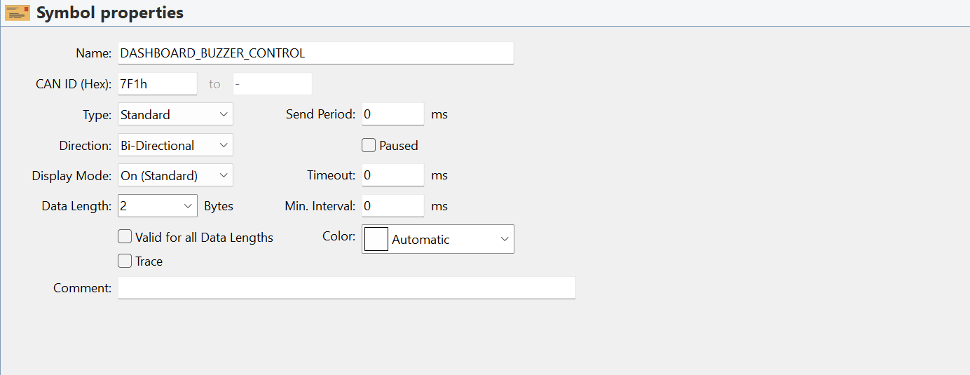
CAN Receive
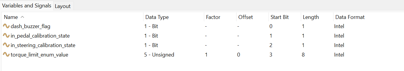
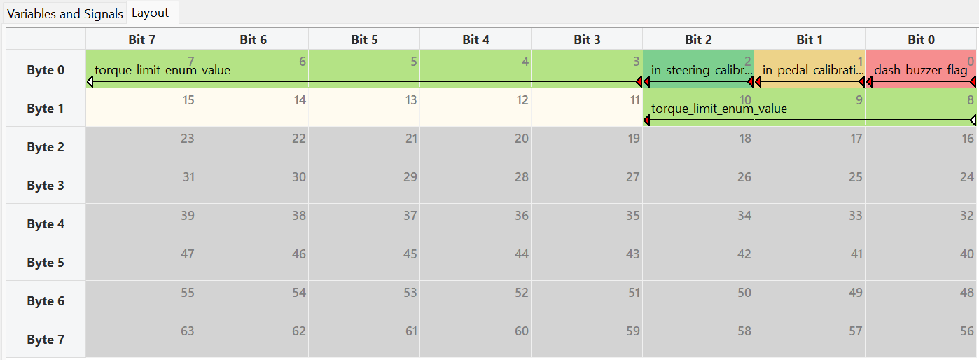
void VCRInterface::receive_dash_control_data(const CAN_message_t &can_msg)
{
    DASHBOARD_BUZZER_CONTROL_t unpacked_msg;
    Unpack_DASHBOARD_BUZZER_CONTROL_hytech(&unpacked_msg, can_msg.buf, can_msg.len);    //NOLINT

    if (unpacked_msg.dash_buzzer_flag) {
        BuzzerController::getInstance().activate(millis());
    }

    _is_in_pedals_calibration_state = unpacked_msg.in_pedal_calibration_state;
    _is_in_steering_calibration_state = unpacked_msg.in_steering_calibration_state;

    if (unpacked_msg.torque_limit_enum_value < ((int) TorqueLimit_e::TCMUX_NUM_TORQUE_LIMITS)) // check for validity
    {
        _torque_limit = (TorqueLimit_e) unpacked_msg.torque_limit_enum_value;
    }
}
VCR System Design
CAN Receive
void VCFInterface::receive_dashboard_message(const CAN_message_t &msg, unsigned long curr_millis)
{
    DASH_INPUT_t dash_msg;
    Unpack_DASH_INPUT_hytech(&dash_msg, &msg.buf[0], msg.len);
    _curr_data.dash_input_state.btn_dim_read_is_pressed = dash_msg.dim_button;
    _curr_data.dash_input_state.preset_btn_is_pressed = dash_msg.preset_button; // pedal recalibration button
    _curr_data.dash_input_state.mc_reset_btn_is_pressed = dash_msg.motor_controller_cycle_button;
    _curr_data.dash_input_state.start_btn_is_pressed = dash_msg.start_button;
    _curr_data.dash_input_state.data_btn_is_pressed = dash_msg.data_button_is_pressed;
    // _curr_data.dash_input_state.left_paddle_is_pressed = dash_msg.left_shifter_button;
    // _curr_data.dash_input_state.right_paddle_is_pressed = dash_msg.right_shifter_button;
    // _curr_data.dash_input_state.mode_btn_is_pressed = dash_msg.mode_button; // change torque limit
    _curr_data.dash_input_state.dial_state = static_cast<ControllerMode_e>(dash_msg.dash_dial_mode);
}
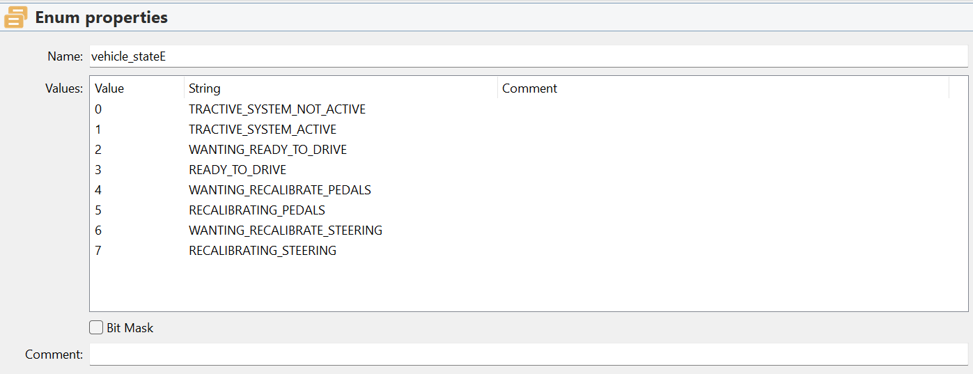
State Machine
VehicleState_e VehicleStateMachine::tick_state_machine(unsigned long current_millis)
{
    switch (_current_state)
    {
        case VehicleState_e::WANTING_RECALIBRATE_STEERING:
        {
            _command_drivetrain(false, false);

            if (!_is_calibrate_steering_button_pressed())
            {
                _set_state(VehicleState_e::TRACTIVE_SYSTEM_NOT_ACTIVE, current_millis);
            }

            if (_is_calibrate_steering_button_pressed() && (current_millis - _last_entered_steering_waiting_state_ms > 3000))
            {
                _set_state(VehicleState_e::RECALIBRATING_STEERING, current_millis);
            }

            break;
        }
        case VehicleState_e::RECALIBRATING_STEERING:
        {
            _command_drivetrain(false, false);

            if (!_is_calibrate_steering_button_pressed())
            {
                _set_state(VehicleState_e::TRACTIVE_SYSTEM_NOT_ACTIVE, current_millis);
            }

            if (_is_calibrate_steering_button_pressed())
            {
                _send_recalibrate_steering_message();
            }

            break;
        }
    }
    return _current_state;
}

void VehicleStateMachine::_set_state(VehicleState_e new_state, unsigned long curr_millis)
{
    _handle_exit_logic(_current_state, curr_millis);
    _current_state = new_state;
    _handle_entry_logic(_current_state, curr_millis);
}

void VehicleStateMachine::_handle_exit_logic(VehicleState_e prev_state, unsigned long curr_millis)
{
    switch (prev_state)
    {
        case VehicleState_e::WANTING_RECALIBRATE_STEERING:
            _last_entered_steering_waiting_state_ms = 0;
            break;
        case VehicleState_e::RECALIBRATING_STEERING:
            _last_entered_steering_waiting_state_ms = 0;
            break;
        default:
            break;
    }
}

void VehicleStateMachine::_handle_entry_logic(VehicleState_e new_state, unsigned long curr_millis)
{
    switch (new_state)
    {
        case VehicleState_e::WANTING_RECALIBRATE_STEERING:
            _last_entered_steering_waiting_state_ms = curr_millis;
            break;
        case VehicleState_e::RECALIBRATING_STEERING:
            break;
        default:
            break;
    }
}
CAN Send
void VCFInterface::send_buzzer_start_message()
{
    DASHBOARD_BUZZER_CONTROL_t ctrl = {};
    ctrl.dash_buzzer_flag = true;
    ctrl.in_pedal_calibration_state = false;
    ctrl.in_steering_calibration_state = false;
    ctrl.torque_limit_enum_value = 0xFF; // MAX_VALUE indicates "ignore this value" //NOLINT
    CAN_util::enqueue_msg(&ctrl, &Pack_DASHBOARD_BUZZER_CONTROL_hytech, VCRCANInterfaceImpl::telem_can_tx_buffer);
    Serial.println("BUZZER START MESSAGE SENT");
}
void VCFInterface::send_recalibrate_steering_message()
{
    DASHBOARD_BUZZER_CONTROL_t ctrl = {};
    ctrl.dash_buzzer_flag = false;
    ctrl.in_pedal_calibration_state = false;
    ctrl.in_steering_calibration_state = true;
    ctrl.torque_limit_enum_value = 0xFF; // MAX_VALUE indicates "ignore this value" //NOLINT
    CAN_util::enqueue_msg(&ctrl, &Pack_DASHBOARD_BUZZER_CONTROL_hytech, VCRCANInterfaceImpl::telem_can_tx_buffer);
}
void VCFInterface::enqueue_vehicle_state_message(VehicleState_e vehicle_state, DrivetrainState_e drivetrain_state, bool db_is_in_ctrl)
{
    CAR_STATES_t state = {};
    state.vehicle_state = static_cast<uint8_t>(vehicle_state);
    state.drivetrain_state = static_cast<uint8_t>(drivetrain_state);
    state.drivebrain_in_control = db_is_in_ctrl;
    CAN_util::enqueue_msg(&state, &Pack_CAR_STATES_hytech, VCRCANInterfaceImpl::telem_can_tx_buffer);
}
Car Messaging System
PCAN Library
Ethernet Messaging
// VCF Ethernet Interface — packing steering data into outbound Ethernet message
hytech_msgs_VCFData_s VCFEthernetInterface::make_vcf_data_msg(ADCInterface &ADCInterfaceInstance, DashboardInterface &dashInstance, PedalsSystem &pedalsInstance, SteeringSystem &steeringInstance)
{
    out.steering_system_data.analog_raw = steeringInstance.get_steering_system_data().analog_raw;
    out.steering_system_data.digital_raw = steeringInstance.get_steering_system_data().digital_raw;
    out.steering_system_data.analog_steering_angle = steeringInstance.get_steering_system_data().analog_steering_angle;
    out.steering_system_data.digital_steering_angle = steeringInstance.get_steering_system_data().digital_steering_angle;
    out.steering_system_data.output_steering_angle = steeringInstance.get_steering_system_data().output_steering_angle;
    out.steering_system_data.analog_steering_velocity_deg_s = steeringInstance.get_steering_system_data().analog_steering_velocity_deg_s;
    out.steering_system_data.digital_steering_velocity_deg_s = steeringInstance.get_steering_system_data().digital_steering_velocity_deg_s;
    out.steering_system_data.digital_oor_implausibility = steeringInstance.get_steering_system_data().digital_oor_implausibility;
    out.steering_system_data.analog_oor_implausibility = steeringInstance.get_steering_system_data().analog_oor_implausibility;
    out.steering_system_data.sensor_disagreement_implausibility = steeringInstance.get_steering_system_data().sensor_disagreement_implausibility;
    out.steering_system_data.dtheta_exceeded_analog = steeringInstance.get_steering_system_data().dtheta_exceeded_analog;
    out.steering_system_data.dtheta_exceeded_digital = steeringInstance.get_steering_system_data().dtheta_exceeded_digital;
    out.steering_system_data.both_sensors_fail = steeringInstance.get_steering_system_data().both_sensors_fail;
    out.steering_system_data.interface_sensor_error = steeringInstance.get_steering_system_data().interface_sensor_error;
}

// VCF receiving VCR data over Ethernet
void VCFEthernetInterface::receive_pb_msg_vcr(const hytech_msgs_VCRData_s &msg_in, VCFData_s &shared_state, unsigned long curr_millis) {
    shared_state.system_data.buzzer_is_active = msg_in.buzzer_is_active;
}

// ── HT-Proto Repository ─────────────────────────────────────────────────────
// Protobuf schema — compiled into C structs used on VCF and drivebrain

syntax = "proto3";
package hytech_msgs;

message SteeringSystemData_s
{
    uint32 analog_raw = 1;
    uint32 digital_raw = 2;

    float analog_steering_angle = 3;
    float digital_steering_angle = 4;
    float output_steering_angle = 5;

    float analog_steering_velocity_deg_s = 6;
    float digital_steering_velocity_deg_s = 7;

    bool digital_oor_implausibility = 8;
    bool analog_oor_implausibility = 9;
    bool sensor_disagreement_implausibility = 10;
    bool dtheta_exceeded_analog = 11;
    bool dtheta_exceeded_digital = 12;
    bool both_sensors_fail = 13;
    bool interface_sensor_error = 14;
}

message VCFData_s
{
    FrontLoadCellData_s front_loadcell_data = 1;
    FrontSusPotData_s front_suspot_data = 2;
    SteeringSensorData_s steering_data = 3;
    BrakePressureSensorData_s brake_pressure_data = 4;
    DashInputState_s dash_input_state = 5; // Direct button signals from the dashboard IOExpander
    VCFEthernetLinkData_s vcf_ethernet_link_data = 6;
	SteeringSystemData_s steering_system_data = 7;
    PedalsSystemData_s pedals_system_data = 8;
    VCFShutdownSensingData_s vcf_shutdown_data = 9;
    FWVersionInfo_s firmware_version_info = 10;
    Versions msg_versions = 11;
}
Outcome
Steering system correctly outputted converted angle values, plausibility checks, and ran recalibration through checking vehicle state machine. With the outputted values sent to drivebrain through CAN & Ethernet messaging, we were able to implement “mode 4”, which intakes steering values, tire load cells, pedals data, and outputs a calculated torque to each wheel. Because of the steering system enabling “mode 4”, HyTech’s vehicle HTX was able to decrease 0.2 seconds on average in the skid pad event at Formula South on April 11th, 2026.